Standard Shape Library
Parameter |
Data |
Units |
Type |
Description |
|---|---|---|---|---|
AnalysisMethod |
LRFR |
text |
LFR or LRFR (default is LRFR) |
|
AnalysisMode |
2DL |
text |
2DL or 2DT (for transverse) Default is 2D. (Legacy 2DL=2D) |
|
AutoFactBuild |
N |
chr |
[Y|N] Automatic Factor builder. If Y rebuild ALL factors input per standard set for LFR and LRFR. |
|
AutoLLBuild |
N |
chr |
[Y|N] Automatic Live Load builder. If Y rebuild ALL live load input per standard set for LFR and LRFR. (ONLY for 2DL mode) |
|
DLMult |
1 |
real |
Dead Load multiplyer. Factor to be applied to computed member gravity load. |
|
DLNetSection |
Y |
chr |
[Y|N] Use section with hand holes removed for gravity load calculations. |
|
FilterByMbrType |
Y |
chr |
[Y|N] Y=Filter Filter analysis by presence of truss members. If truss mbrs then ONLY do Truss analysis. If NO Truss mbrs then ONLY do line mbr analysis |
|
IncludeDoubleTandem |
N |
chr |
[Y|N] Include double tandem with HL93? Default for WSDOT is N. CalTrans includes this, so state Y |
|
IntrBeam |
Y |
chr |
[Y|N] for LRFR is this an interior beam analysis |
|
MRatio |
8 |
real |
Modular Ratio Override. If not zero use this value instead of computed Es/Ec |
|
MaxAllowDeformation |
1 |
FET |
real |
(Feet) Maximum allowable deformation during load analysis. |
Phi_b |
1.00 |
real |
LRFR Resistance factor for bearings (AASHTO 6.5.4.2 – 2020 edition) |
|
Phi_bs |
0.80 |
real |
LRFR Resistance factor for block shear (AASHTO 6.5.4.2 – 2020 edition) |
|
Phi_c |
0.95 |
real |
LRFR Resistance factor for axial compression (AASHTO 6.5.4.2 – 2020 edition) |
|
Phi_f |
1.00 |
real |
LRFR Resistance factor for flexure (AASHTO 6.5.4.2 – 2020 edition) |
|
Phi_s |
0.80 |
real |
LRFR Resistance factor for bolts in shear (AASHTO 6.5.4.2 – 2020 edition) |
|
Phi_system |
1.00 |
real |
LRFR System factor for flexure and axial (WSDOT BDM Chapter 13, section 13.1.1.C – 2023 edition) |
|
Phi_u |
0.80 |
real |
LRFR Resistance factor for tension, fracture in net section (AASHTO 6.5.4.2 – 2020 edition) |
|
Phi_v |
1.00 |
real |
LRFR Resistance factor for shear (AASHTO 6.5.4.2 – 2020 edition) |
|
Phi_vu |
0.80 |
real |
LRFR Resistance factor for shear, rupture in connection elements (AASHTO 6.5.4.2 – 2020 edition) |
|
Phi_y |
0.95 |
real |
LRFR Resistance factor for tension, yielding in gross section (AASHTO 6.5.4.2 – 2020 edition) |
|
RatePlotLimit |
2.00 |
real |
When plotting rating, limit the scale to this value |
|
RiderDist |
0 |
FET |
real |
Distance per iteration for lane load rider (default if 0 is tenth of span). |
Rp |
1 |
real |
Reduction factor for holes. Use 0.90 for bolt holes punched full size and 1.0 for bolt holes drilled full size or subpunched and reamed to size |
|
Rpt2DTForces |
N |
chr |
[Y|N] Y=Generate a 2DT_Forces report if 2DT analysis. |
|
RptCap |
N |
chr |
[Y|N] Y=Generate capacity and rating calculations file. |
|
RptCapTrace |
N |
chr |
[Y|N] Y=Generate capacity and rating calculations file. |
|
RptCapTraceTenthPts |
N |
chr |
[Y|N] If RptCapTrace is Y then reduce line member trace to near tenth points only. |
|
RptFEA |
N |
chr |
[Y|N] Y=Generate FEA forces file. (Warning, file can be quite large!) |
|
RptFEACtrlTruck |
N |
chr |
[Y|N] Y=If generating a FEA file also include controlling truck information |
|
RptInfSurf |
N |
text |
[Y/N] Y=Influence surface report. (warning large file generated) |
|
RptPrependMethod |
N |
chr |
[Y|N] Y=Report file names will be prepended with either LFR or LRFR |
|
RptSect |
Y |
chr |
[Y|N] Y=Generate section properties report. |
|
RptSummary |
Y |
chr |
[Y|N] Y=Generate Rating summary report. |
|
RptTruckLoading |
N |
text |
[Y|mbr] Y=ALL or mbr=Name of Member to report raw trucking loading. Leave blank to disable. (warning large file generated) |
|
RptTrussForces |
N |
text |
[Y|N] Y=Generate a truss force report. |
|
ShrCapFct |
Y |
chr |
[Y|N] Y=For Inv. & Opr. Capacity, use Inv. factors for M in AASHTO eq. 10-118. |
|
StopAtDL |
N |
chr |
[Y|N] Y= Run bridge only up through Deadload analysis. |
|
TrussDLonEnds |
N |
chr |
[Y|N] Y= Gravity for truss mbrs applied at end nodes only not as linear load. |
|
WetSlab |
Y |
chr |
[Y|N] Y= Use a very low E for slab plates in final DL stage. |
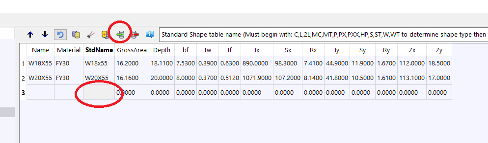
PURPOSE
Entry of Standard Shapes that are extrusions normally found in the AISC handbook.
Parameters
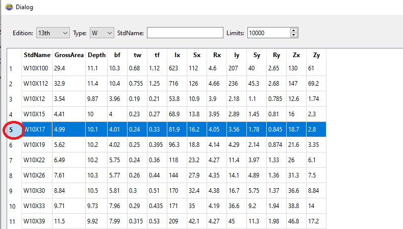
Properties for most common standard shapes can be found using the The AISC shapes table in the Tools menu. See discussion about the AISC tool below.
StdName MUST begin with a standard shape letter indicator:
The entered values are used to compute the shape properties, dependant on the shape type.
Field |
Type |
Units |
Description |
|---|---|---|---|
Name |
text |
User defined name |
|
Material |
text |
Material Library Reference |
|
StdName |
text |
Standard Shape table name (Must begin with: C,L,2L,MC,MT,P,PX,PXX,HP,S,ST,W,WT to determine shape type then entered values used for section proerties) |
|
GrossArea |
real |
IN2 |
Gross Area |
Depth |
real |
INC |
Depth of shape |
bf |
real |
INC |
Flange Width |
tw |
real |
INC |
Web thickness |
tf |
real |
INC |
Flange thickness |
Ix |
real |
IN4 |
Moment of inertia major plane of bending (About local Z axis) |
Sx |
real |
IN3 |
Section modulus for Ix |
Rx |
real |
INC |
Radius of gyration with respect to the local Z-Z axis |
Iy |
real |
IN4 |
Moment of inertia minor plane of bending (About local Y axis) |
Sy |
real |
IN3 |
Section modulus for Iy |
Ry |
real |
INC |
Radius of gyration with respect to the local Y-Y axis |
Zx |
real |
IN3 |
Plastic modulus about X-X axis |
Zy |
real |
IN3 |
Plastic modulus about Y-Y axis |
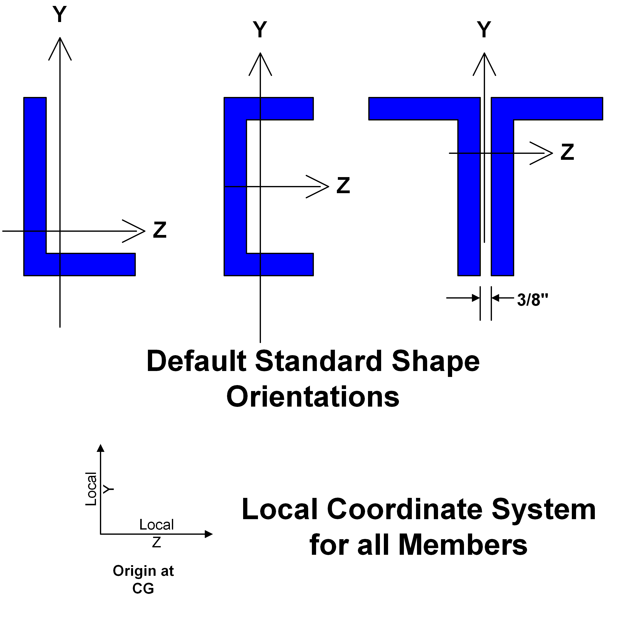
Default member orientation
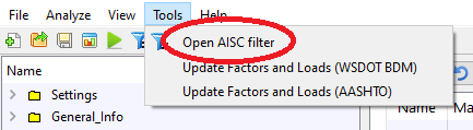
The AISC shapes table
The AISC shapes table is included with the BRIDG program for easy entry of standard shapes. To use the tool: