Note
Go to the end to download the full example code.
Tutorial 2 - Using Meshers
This tutorial shows how to utilize Mesher classes
to quickly create your structural model.
The key difference to the technique demonstrated in Tutorial 1 - Creating a Model
is that Mesher classes describe a general geometry, not finite elements and nodes,
and provide methods to mesh those geometric domains with beam-, frame-, or plate-elements.
The preparation stage
Before building a model, we need to load the used components.
Every model needs one System instance. Furthermore,
we are going to load several Node and Element instances for use throughout this tutorial.
We will load the respective Mesher class right where we demonstrate their use.
Loading those class definitions requires the following:
import numpy as np

from femedu.domain import System
# line-type elements
from femedu.elements.linear import Frame2D
# triangle plate-type elements
from femedu.elements.linear import Triangle, Triangle6
from femedu.elements.diffusion import Triangle as ThermalTriangle
# quadrilateral plate-type elements
from femedu.elements.linear import Quad, Quad9
# elastic materials
from femedu.materials import ElasticSection, PlaneStress, PlaneStrain, Thermal
For more detail on the loaded types, read Element classes and Material class.
Curve Meshers
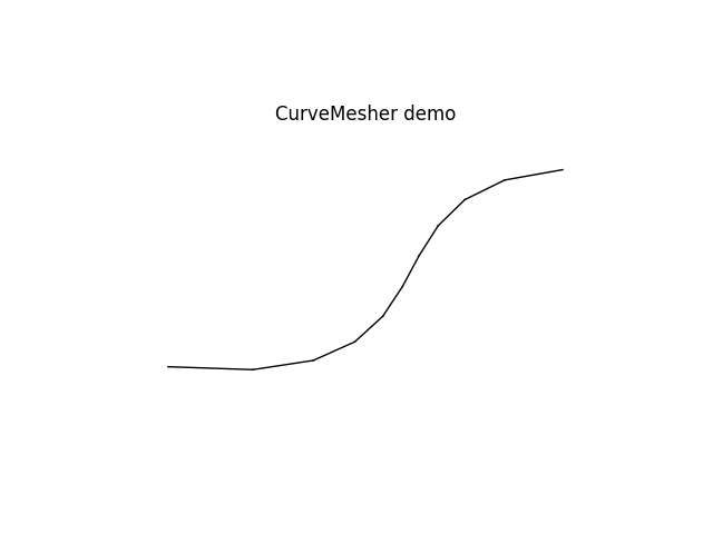
This mesher takes two or more points to create an interpolated smooth curve using B-splines.
The CurveMesher.mesh() generates nodes and elements along that curve and adds them to your model.
from femedu.mesher import CurveMesher

model = System()
mesher = CurveMesher(model, (0,0),(1.5,.25),(2,1),(3.,1.5))
mesher.mesh(10, Frame2D, ElasticSection())
model.plot(factor=0.0, title='CurveMesher demo')

Read CurveMesher class for more information on this Mesher()
Triangle Domain Meshers
This mesher defines a triangular domain out of a minimum of three (3) corner points. You may define up to three additional points, where each additional point defines the location of the mid-point along the first (pt0 to pt1), second (pt1 to pt2), and third (pt2 to pt0) side, respectively. Sides and the respective domain will be interpolated using a full quadratic polynomial.
Entering None in place of a point will place a midpoint at the half point along a straight side.
It makes sense to parametrize any mesh generation to easily perform mesh refinement, change dimensions and/or units, or modify material parameters for the entire model.
from femedu.mesher import PatchMesher, TriPatchMesher

model = System()

# ========== setting mesh parameters ==============
Nx = 6        # number of elements per side
Lx = 100.0    # length of plate in the x-direction
Ly =  60.0    # length of plate in the y-direction

# ========== setting material parameters ==============
params = dict(
    E  = 20000.,    # Young's modulus
    nu = 0.250,     # Poisson's ratio
    t  = 1.00       # thickness of the plate
)
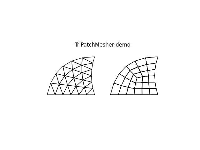
We shall generate two equally shaped domains to side-by-side demonstrate different meshing options.
# create reference points
pt0 = (0.25*Lx, 0); pt1 = (Lx, 0.0); pt2 = (Lx, Ly); pt4 = (0.95*Lx, 0.5*Ly); pt5 = (0.5*Lx, 0.75*Ly)
pt6 = (1.25*Lx, 0); pt7 = (2.00*Lx, 0.0); pt8 = (2.00*Lx, Ly); pt10 = (1.95*Lx, 0.5*Ly); pt11 = (1.5*Lx, 0.75*Ly)

mesher1 = TriPatchMesher(model,
                         pt0, pt1, pt2,  # corner nodes
                         None, pt4, pt5,  # mid-side nodes
                         )
mesher2 = TriPatchMesher(model,
                         pt6, pt7, pt8,  # corner nodes
                         None, pt10, pt11,  # mid-side nodes
                         )
The above code generated the geometric domain, while the following commands will generate nodes and finite elements within those two domains. We shall mesh the first domain with triangles, the second with quadrilaterals.
nodes1, elements1 = mesher1.triangleMesh(Nx, Triangle, PlaneStress(params))
nodes2, elements2 = mesher2.quadMesh(Nx, Quad, PlaneStress(params))
Note that the user needs to provide a suitable, i.e., with proper shape, element and material model. The given element type will be used when generating elements. Each element will receive a unique clone of the provided material object in the process.
Note
The mesher methods triangleMesh() and quadMesh() will return
a list of all created nodes, followed by a list of all created elements. Those
nodes and elements have been added to the model already and do not require any
further action by the user. They are provided for convenience and/or validation only.
If that information is not needed, simply call the meshing methods without assigning their return value to local variables.
model.plot(factor=0.0, title='TriPatchMesher demo')

Read TriPatchMesher class for more information on this Mesher()
Quadrilateral Domain Meshers
This mesher defines a quadrilateral domain out of a minimum of four (4) corner points. You may define up to three additional points, where each additional point defines the location of the mid-point along the first (pt0 to pt1), second (pt1 to pt2), and third (pt2 to pt0) side, respectively. Sides and the respective domain will be interpolated using a full quadratic polynomial.
Entering None in place of a point will place a midpoint at the half point along a straight side.
from femedu.mesher import PatchMesher, TriPatchMesher

model = System()

# ========== setting mesh parameters ==============
Nx = 6  # number of elements through the wall
Ny = 4  # number of elements parallel to the wall
Lx = 10.00  # wall thickness in m
Ly =  5.00  # wall thickness in m
Ri =  5.00
Ro = Ri + Lx
alpha = np.radians(45.0)
dX = 1.2*(Ro - Ri*np.cos(alpha))

pts = (
    ( Ri,  0),  # 0
    ( Ro,  0),  # 1
    ( Ri*np.cos(alpha), Ri*np.sin(alpha)),  # 2
    ( Ro*np.cos(alpha), Ro*np.sin(alpha)),  # 3
    ( Ri*np.cos(alpha/2), Ri*np.sin(alpha/2)),  # 4
    ( Ro*np.cos(alpha/2), Ro*np.sin(alpha/2)),  # 5
)
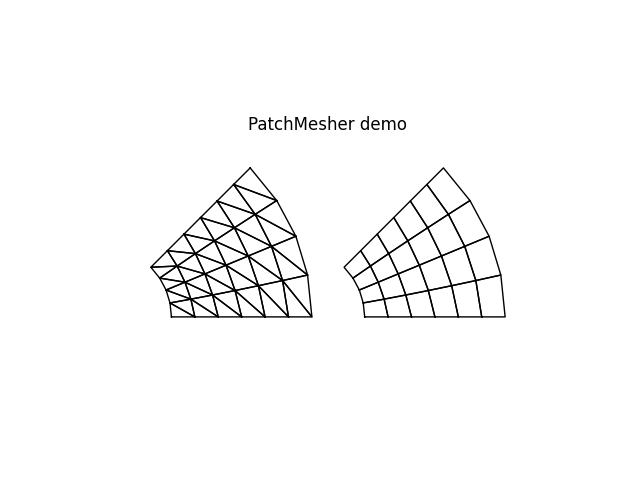
The above code generated the geometric domain, while the following commands will generate nodes and finite elements within that domain. We shall mesh this domain with triangles.
Note that the user needs to provide a suitable, i.e., with proper shape, element and material model. The given element type will be used when generating elements. Each element will receive a unique clone of the provided material object in the process.
mesher1 = PatchMesher(model, pts[0], pts[1], pts[3], pts[2], None, pts[5], None, pts[4])
nodes1, elements1 = mesher1.triangleMesh(Nx, Ny, ThermalTriangle, Thermal(params))
Warning: unknown parameter E found in parameter list - ignored
Warning: unknown parameter nu found in parameter list - ignored
Warning: unknown parameter t found in parameter list - ignored
Warning: unknown parameter A found in parameter list - ignored
Warning: unknown parameter fy found in parameter list - ignored
Let’s generate a second identical domain but mesh it with quadrilaterals instead.
pts = (
    ( dX+Ri,  0),  # 0
    ( dX+Ro,  0),  # 1
    ( dX+Ri*np.cos(alpha), Ri*np.sin(alpha)),  # 2
    ( dX+Ro*np.cos(alpha), Ro*np.sin(alpha)),  # 3
    ( dX+Ri*np.cos(alpha/2), Ri*np.sin(alpha/2)),  # 4
    ( dX+Ro*np.cos(alpha/2), Ro*np.sin(alpha/2)),  # 5
)

mesher2 = PatchMesher(model, pts[0], pts[1], pts[3], pts[2], None, pts[5], None, pts[4])
nodes2, elements2 = mesher2.quadMesh(Nx, Ny, Quad, PlaneStress(params))

model.plot(factor=0.0, title='PatchMesher demo')

Note
The mesher methods triangleMesh() and quadMesh() will return
a list of all created nodes, followed by a list of all created elements. Those
nodes and elements have been added to the model already and do not require any
further action by the user. They are provided for convenience and/or validation only.
If that information is not needed, simply call the meshing methods without assigning their return value to local variables.
Read PatchMesher class for more information on this Mesher()
Total running time of the script: (0 minutes 0.090 seconds)