Input Bearing Stiffener
Table tbBearingStiffener
PURPOSE
Define bearing stiffeners along a stringer.
Reference the theory flow chart,SS-6.3, for how bearing capacity and ratings are computed. Because the 1.7 working stress to ultimate design conversion factor (see theory) is not calibrated for overload, the overload factors are conservatively not used.
The forces for bearings are taken from the maximum positive “Y” constrained reaction of the specified COGO point. If this point is not constrained in the “Y” direction then there will not be any forces.
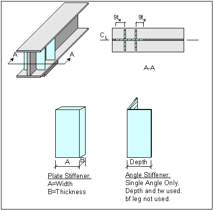
The geometry of the stiffener arrangement is theoretical. The Cogo point defined as the bearing stiffener location is used for force collection, and the computation of the stiffener geometry is not limited by the fact that this point may be on the member end. The full web contact length is computed using the “Num Stiffeners”, “Spacing”, and web thickness values. Please see the graphic below.
Note, bearing stiffeners are not used as shear stiffeners!
Parameters
Field |
Type |
Units |
Description |
|---|---|---|---|
MbrLine |
text |
Member line name |
|
CogoPt |
text |
Support point on member. |
|
Shape |
text |
Reference to plate or angle. |
|
Num |
int |
Number of stiffener pairs (assume each side of web.) |
|
Spacing |
real |
INC |
Spacing between stiffeners. |
K |
real |
Effective Length factor (default = 1.00 if cell is blank or has value of 0.0) |
|
Cope |
real |
INC |
Cope distance on each stiffener end. |
RateFactor |
text |
Rating Factors |
|
CxS |
real |
Condition factor * System factor (phi_c * phi_s) (default = 1.00 if cell is blank or has value of 0.0) |