Input Web Haunch Definition
Table tbWebHaunchDef
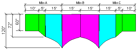
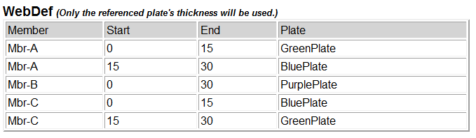
PURPOSE Automatic haunched member placement is possible when you use the Flange Placement, the Web Placement and Web Haunch Definition tables to define a W1, A3, or A3A type shape for a line member.
The haunch calculations are for the web plate depth not the entire shape depth. So you will need to take this into account when setting the depth factors. The flanges and cover plates are added to the ‘haunched’ web plate to build up the complete section.
The haunched section are discrete and computed at sections defined by number of divisions between the start and end of the haunch section. The minimum distance is one (1) foot.
Parameters
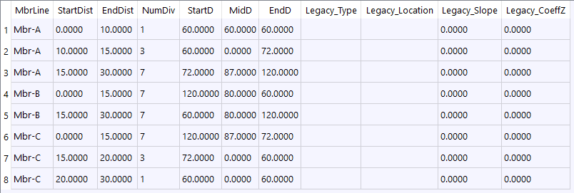
tbWebHaunchDef Field
Type
Units
Description
MbrLine
text
Member line name
StartDist
real
FET
Distance from start of member line
EndDist
real
FET
Distance from start of member line to end of this shape placement. (Entry optional)
NumDiv
int
Number of divisions. Use 0.0 for maximum number of divisions. (Distance for each section is limited to 1.0 feet. )
StartD
real
INC
Starting plate depth
MidD
real
INC
Plate depth at mid point. If MidD=0.0 then assume straight line
EndD
real
INC
Ending plate depth
Legacy_Type
chr
Legacy method not used anymore. Here for backward compatibility. [H|S] H=Haunched, S=Sloped
Legacy_Location
chr
Legacy method not used anymore. Here for backward compatibility. [S|E] Location of slope (S=Start, E=End)
Legacy_Slope
real
Legacy method not used anymore. Here for backward compatibility. Initial Slope when Type=Haunch
Legacy_CoeffZ
real
FT2
Legacy method not used anymore. Here for backward compatibility. Coefficient Z (y=A*X^Z) when Type=Haunch
Example